1971 Model Engineer - Build Your Own Teasmade
Article by S Orme on building a tea-maker, published in Model Engineer, March 1971.

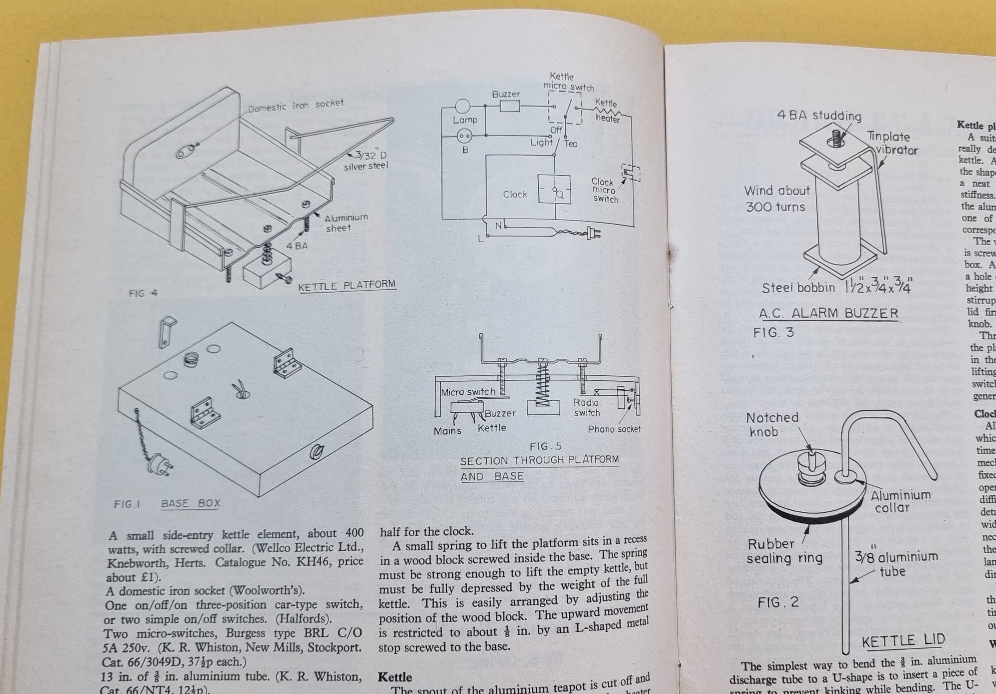
On 19 March 1971, Model Engineer featured an article on building a tea-maker (pages 281-283). The article was written by S Orme, (probably a contributor). Unfortunately, a complete illustration of the model was not included, but there were six diagrams to explain the construction. The component list is an eye-opener. It's amazing what parts and equipment S Orme thinks will be in the standard junk box and need not be listed!
An Automatic Tea-Maker, by S. Orme.
This is an interesting project, resulting in a reliable article highly regarded by those who appreciate an extra bit of morning comfort. The principle is as follows:
An electric kettle, airtight except for a 1/32 inch hole in the lid, contains a U-shaped discharge tube. When the water boils, steam pressure forces the water through the U-tube into any convenient teapot. The 1/32 inch hole is necessary, otherwise expanding warm air would force some water out before it was boiling. The kettle fits onto a spring-loaded hinged platform. The weight of the full kettle forces the platform right down and holds a micro-switch in the "closed" position.
When boiling water transfers to the teapot, the reduction in weight allows the platform to rise about 1/8th inch and opens the micro-switch, thus switching the kettle off.
The rising platform also switches on an alarm buzzer, a lamp, and, if you wish, a radio. A normal electric alarm clock is modified to operate another micro-switch and this starts the sequence at the pre-set time.
The general layout is clearly shown in the photographs. The construction is quite straightforward, and none of the dimensions given is at all critical.

Components required
- Any electric alarm clock.
- A cheap thin aluminium teapot with a push-on lid (Woolworth's).
- A small side-entry kettle element, about 400 watts, with screwed collar. (Wellco Electric Ltd., Knebworth, Herts. Catalogue no. KH46, price about £1).
- A domestic iron socket (Woolworth's).
- One on/off/on three-position car-type switch, or two simple on-off switches (Halfords).
- Two micro-switches, Burgess type BRL C/O 5A 250v. (K R Whiston, New Mills, Stockport. Cat. 66/3049D, 37 1/2 p each).
- 13 in. of 3/8 in. aluminium tube. (K R Whiston, Cat. 66/NT4, 12 1/2 p).
- One 40 watt lamp and lampholder.
The few remaining items can usually be found in the junk box. The complete outfit cannot be sold cheaply because of the cost of these components. Shop prices seem to be between £15 and £30. Constructional details are as follows:
Base
This is a simple inverted box of 1/4 in. thick wood, about 12 in. x 6 in. x 2 in., open at the bottom, and suitably painted. Half of the top is taken up by the kettle platform, leaving the other half for the clock.
A small spring to lift the platform sits in a recess in a wood block screwed inside the base. The spring must be strong emough to lift the empty kettle, but must be fully depressed by the weight of the full kettle. This is easily aranged by adjusting the position of the wood block. The upward movement is restricted to about 1/8 in. by an L-shaped metal stop screwed to the base.
Kettle
The spout of the aluminium teapot is cut off and the resulting hole enlarged to take the heater element. Soft sealing washers are required inside and outside the kettle, and screwing up the collar should squeeze a flat in the this curved aluminium. A touch of gasket cement may be required to prevent leaks.
The drop-on lid must be provided with a rubber sealing ring (a car oil-filter ring is suitable). A small notch for the retailning clip is filed across the top of the knob - if this is soft plastic it may be better to make a new aluminium knob. Pierce a tiny air-escape hole through the lid, with a needle.
The simplest way to bend the 3/8 in. aluminium discharge tube to a U-shape is to insert a piece of spring to prevent kinking while bending. The U-tube must reach to the bottom of the kettle, and is fixed through the lid with an aluminium collar, sealed with "Araldite" cement - or a screwed pipe union could be used.
Alarm Buzzer
The construction of a very simple and satisfactory alarn buzzer is clearly shown in Fig. 3. This is fixed inside the base by means of the projecting 4 BA studding.
Kettle Platform
A suitable size is 6 in. x 6 in., though this is really determined by the size and shape of the kettle. A piece of stiff aluminium sheet is bent to the shape shown, and the edges turned over to give a neat appearance. Two ridges give increased stiffness. These can be neatly formed by squeezing the aluminium in a vice between two wood blocks, one of which has a groove, and the other a corresponding ridge.
The wooden piece "A", about 6 in. x 3 in. x 1/2 in., is screwed to the aluminium and hinged to the base box. A cut-down domestic iron socket is glued into a hole cut through the wooden piece, at the correct height to receive the kettle prongs. A springy stirrup, made from 3/32 in. silver steel rod, holds the lid firmly in place by clipping into the notched knob.
Three 1 in. 4 BA screws fixed near the edge of the platform project downwards through 1/2 in. holes in the base. The centre screw accomodates the lifting spring and the other two operate the micro-switch and the radio switch. Fig 5. shows the general arrangement of the internal switching.
Clock
All electric alarm clocks contain a snail or cam which releases the buzzer vibrator at the pre-set time. This vibrator is discarded, and the cam mechanism used to operate a second micro-switch fixed to the clock. Since these switches will easily operate with a 1/16 in. movement of the cam, no difficulty should be experienced; but no precise details can be given as electric alarm clocks vary widely from one make to another. It may be necessary to fix the micro-switch on the outside of the clock case, if the interior space is restricted. A lampholder is fixed on top of the clock case, either directly or raised upon a short wooden pillar.
When the tea is ready, the lamp draws its current through the buzzer; but the light is available at any time by direct connection to the mains, thus cutting out the buzzer.
Wiring
Apart from two short flexible wires from the kettle socket (protected by a small cover), all the wiring is concealed in the base box and the clock case. The radio-switch is an optional extra, intended for a battery radio. It consists of two leaf-spring contacts taken from an old relay and connected to a Phono Socket.
The radio-switch and micro-switch are mounted on small wood blocks screwed inside the base so that they can be tilted up or down slightly to get the correct adjustment. If a mains radio is required, it can be plugged into an additional socket "B", in parallel with the lamp.
Copyright Info
This article may still be within copyright, and I am sharing my transcription here for education and research purposes only. (This may not be used for commercial purposes). I have not been able to identify S Orme to obtain further clearances. He/she mentions 'photographs' in the text, but these were not published alongside the article, and it is unclear who supplied the technical drawings. As they have been presented in 'house style', copyright may relate to Model Engineer. I will remove if requested.
