Repairing an old teasmade clock
Some clock faults can be repaired in a home workshop. Scroll down a little for some workshop advice from Doug and retired teasmaniac Mike Phelan.
Getting help
If you’d rather not get mechanical yourself, a good local clock repairer is normally your first port of call. Unfortunately in our throwaway world, repairers are getting harder and harder to find on the high street, but they are out there waiting to be found, if you look.
Professionals
The main society for clock repairers is the British Horological Institute, where you can find a list of BHI Accredited Repairers, and there are many other repairers out there who are unaccredited, but are suitably qualified and experienced.
Sadly, many professional clock repairers have waiting lists, lofty aspirations, and niche specialisations. They may find teasmade repairs a bit too pedestrian. If you happen upon one of these, don't worry, just ask for recommendations or search again.
Clock Repairs and More who used to deal in teasmade repairs at Clevedon Craft Centre on the edge of Clevedon near Bristol is now closed. Patrick’s telephone was 07904 491665, but I am not sure whether he is still trading.
Amateurs
You may find a clock expert at your local "Men's Shed".
Irreparable clocks
If you have a totally irreparable clock motor, or a teasmade without a clock, electronic timers can be used instead.
Workshop
Here's some advice from Doug and retired teasmaniac Mike Phelan.
Mike kicks things off for us:
First, some terminology
- Clocks have wheels and pinions (old mangles and farm implements have cogs).
- Wheels have arbors mounted on them. All the wheels geared together is a train.
- Arbors have pivots that run in pivot holes
A quick résumé of how a synchronous electric clock works
The clock is simply an electric motor and gearbox. It has no concept of timekeeping itself; the accuracy is because the Grid supplies our power at a precise 50Hz – the mains voltage reverses itself 100 times a second. The clock motor in the D25 has two annular polepieces that surround a coil of fine wire that is connected to the mains; this is called the field. The fine wire and thousands of turns mean that very little current is used.
If you look inside the motor (see later) you can see the annular polepieces have 15 interleaved projections – this gives alternate north and south poles rotating 100 times a second. Inside this is the bit that goes round – the rotor – this has a steel magnet formed as six pairs of alternate poles.
If we spin it somehow, it will lock in to rotate (either direction!) at 50/15 revs per second – 3.33.
How do we spin it? The rotor has pairs of poles that do not fit the field poles exactly, so if we turn on the current, it starts to vibrate until the inertia of the rotor makes it spin. Because there is a 50-50 chance it will spin the wrong way, there is an anti-reversing device in the clock (see below) that gives it an abrupt shove if it tries to reverse.
So, we have an accurate motor – all we need is some gearing to reduce the speed to once a minute, then once an hour, then once in twelve hours – all these to make the hands operate.
Dos and Don’ts – read this even if you are in a hurry
- Don’t wash a clock in solvent without dismantling it – you just rearrange the muck.
- Do use the correct lubricants.
- Don’t lubricate parts that should be dry.
- Treat the field coil with respect – if you find a Teasmade in a damp shed, attic or garage, do not switch it on until it has been in a warm room for a week.
- Don’t squirt WD40 in a clock; apart from anything else, if anyone uses ammoniated clock cleaner, all the brass bits will turn a dirty green, and you will have to spend a week getting it all off!
- Do not scrap D25s or motors with faults – there is not an endless supply, and everything is repairable.
- Also, and this is important. Our mains voltage of 240 can kill! If you are unsure about working on anything that uses the mains, better safe than sorry.
There, that’s the nannies satisfied for now!
Dealing with a noisy clock
Doug takes over to explain more...
The clock is an Achilles heel of the vintage teasmade. By definition the clock must work for the lifetime of the appliance. 24 hours a day – for years without stopping.
All Goblin teasmades 1936-1986 are fitted with synchronous motors and the secret to a long life is to leave them plugged in without interruption for years if possible. Switching them off and on puts a strain on the coil which can lead to failure. So my advice is to let them run, even if away on holiday - it will do no harm.
They are robust units but after many years in a warm atmoshere the bearings run dry and the motor can be heard whirring. If you can hear the clock, it needs attention.
Unplug the unit from the mains. Remove the back and expose the clock motor. It is secured with two screws. Undo these and withdraw the motor with the leads still attached to the unit. Get a can of WD40 or sewing machine oil and spray/pour a little in the lid. Now get a small artist’s brush and pick up a droplet of fluid. Turn the motor from horizontal to vertical and brush the end of the shaft so the fluid runs down inside. Hold like this for a minute or two. Return to horizontal position dangling on the leads. Switch on. The motor should self-start or may be assisted with a turn on the nylon worm gear. It should now be almost silent in operation. Leave running like this for a few minutes and smear a little light grease on the nylon worm. Reassemble and set clock. Note: Applies from 85x series and the clock motor is a 110v unit with a 12k resistor in the circuit. It runs on approximately 90 volts and must never be connected direct to a 240v supply.
What to do if your clock motor stops
If your clock motor has stopped there are two possibilities. First try to see if the motor will turn freely. If the motor does not turn, it probably needs cleaning and lubricating.
- Do not dunk movement in solvent – it MUST be dismantled
- Do not allow WD40 or similar anywhere near any clock
- Do not use any old oil or grease
If the motor turns freely, you need to check if the coil is O/C. It is possible to rewind the coil or get it rewound.
How to Check and Fix a Clock
Mike Phelan © 2006
The following article covers how to check a D25 type clock, and how you can fix any problems. The D25 type clocks are very well made indeed, and should last for centuries!
Tools needed
Selection of screwdrivers, pliers, soldering iron. Cheap multimeter. If you want to do a complete overhaul, pegwood (or pieces of skewer/chopstick). sharp knife, clock oil or Mobil 1, light grease (from motor factor).
Possible faults
Clock does not work at all. There are only two possibilities: there is break in the circuit, or there is a mechanical problem, usually dirt.
To check, do the lights and buzzer work? If not, check the fuse and wiring in the plug. Note that all D25s should have had both original fabric-covered cables replaced – they are all perished and a safety hazard.
If the lights work, turn them off, and then the power. Leave the unit standing as it is. You really need to put a meter across the connections on the live and neutral pins.
If you don’t have a meter, get one – there are plenty for less than £5 – does not even have to be digital, although the latter are advertised at time of writing (12/2005) in Maplin for £2.99. Put one in each pocket! On resistance range, should measure about 8.8K.
Now take the cover off the clock, and remember that terminals are LIVE!
Turn unit on, and look for the rotor field – it is iron, and everything else is brass. Gingerly touch it with an insulated screwdriver keeping away from any exposed terminals and if the coil is intact, you should hear a buzz. If there is, then you may have misread the meter. No buzz? Turn off and measure across the connections to the coil – on the D25, a small tagstrip in the bottom of the case. If no reading, sorry, the coil is duff, and you or someone will have to rewind it.
If the motor is buzzing nicely but does not run, go to the cleaning instructions.
Cleaning and oiling
OK – here we go. Disconnect plug! We’ll assume that you have taken the set-hands knob off (beware – left-hand thread), the back cover and the alarm set knob – right hand thread, you may have to hold the nuts with pliers.
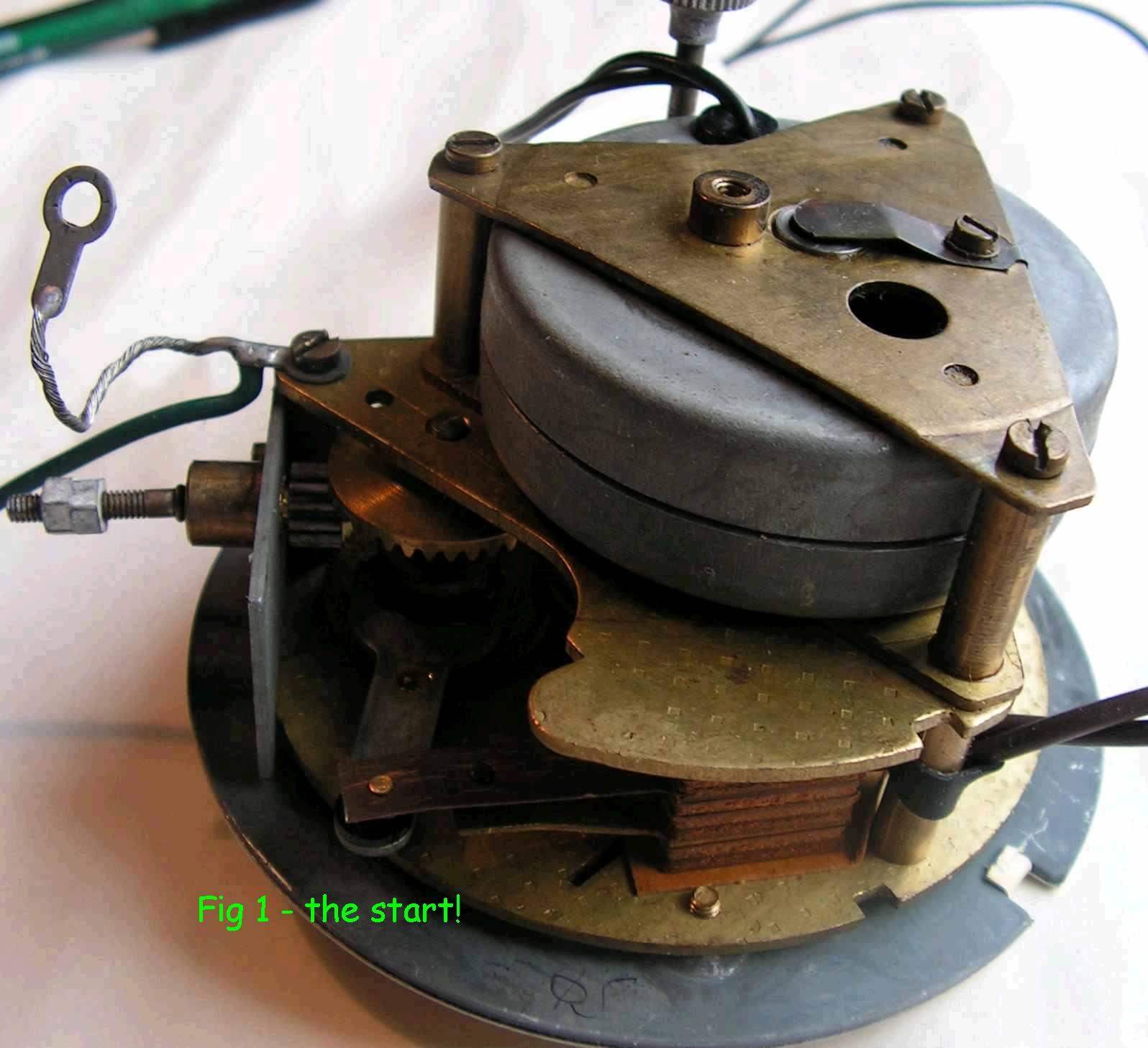
Take the bottom cover off and unsolder the connections to the clock, noting the colours of the wires. The clock will come out after you slacken the three screws and swing the clamps out of the way. The movement will look like this (Fig 1).
You may get away with just cleaning the rotor bearings so that is the first job, anyhow.
Remove the three screws you can see and lift out the rotor plate. Lift off the field, keeping the two halves of the poles together. At this point, beware of any bits of magnetic materials coming near the rotor, which will now be visible in all its glory. (Fig 2). Just to be sure what we mean by magnetic, this could be any ferrous material, not necessarily one that is magnetised, but one that can be attracted by a magnet, such as iron, steel, or cobalt.
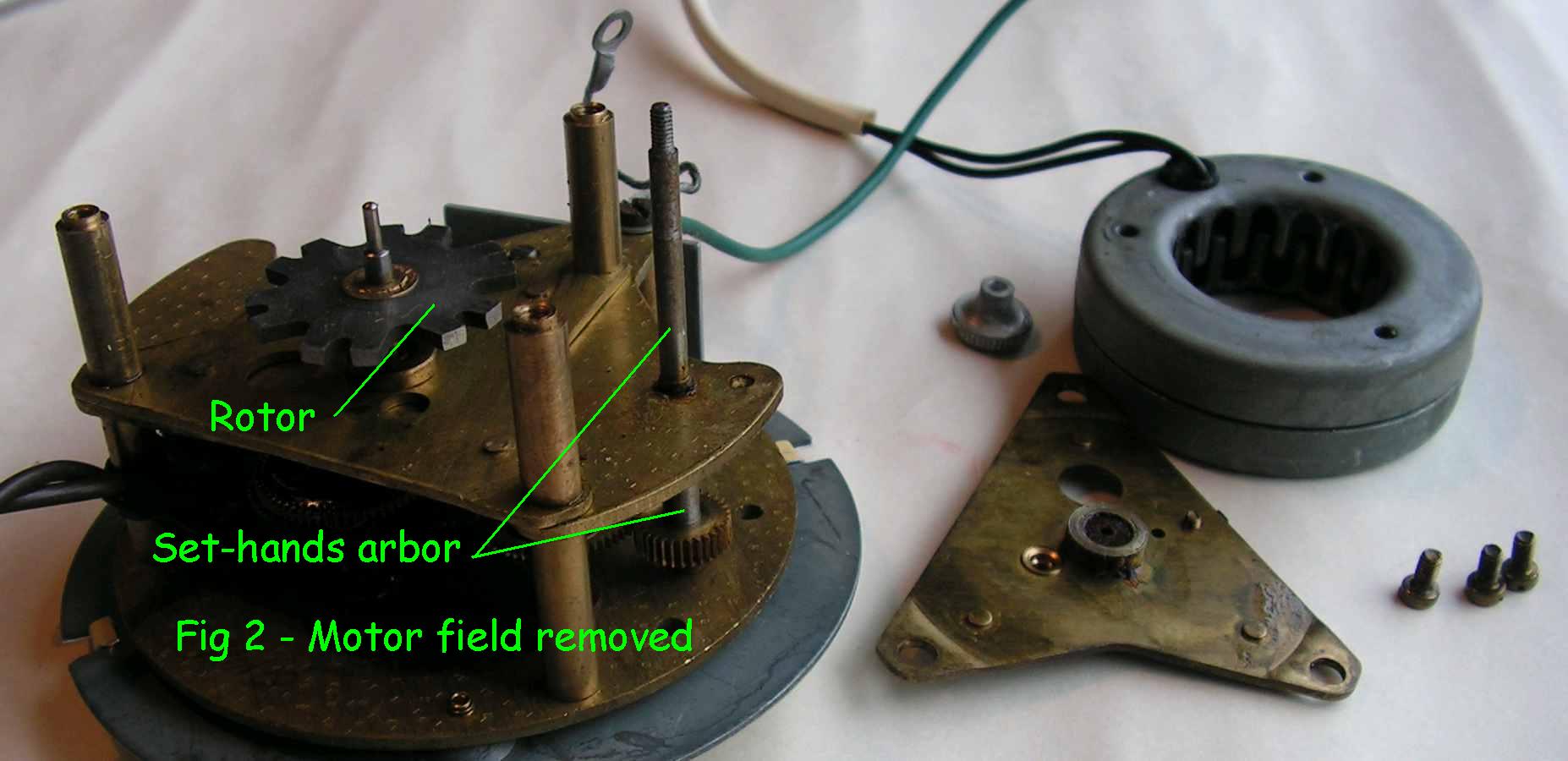
If you unscrew the three pillars by gripping them with a piece of cardboard or similar, the underside rotor plate will come off. At this point, it is worth taking stock. If the only problem is that the rotor is sticky or noisy, you may get away with no further dismantling.
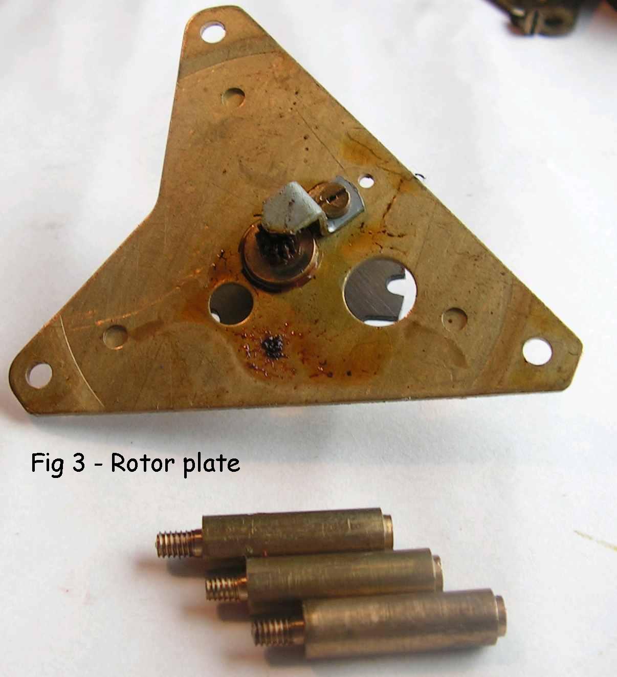
Take off the screw from the bottom plate (Fig 3) and the screw and clip on the top bearing (Fig 1) being careful not to lose the steel disc under it.
The rotor will not come off completely – not a problem. Wash both plates and the other parts you have removed in white spirit or petrol (outside!) and allow to dry, then lubricate and assemble as depicted below, after the full overhaul which you have omitted. If all is OK, congratulations!
A full overhaul
We will assume you are at the stage above where the rotor, field, and both of the plates have been removed.
The next things to remove are the hands and dial. There are four hands, and they are pressed on. The first one, the seconds hand (not second hand, please!) is fairly tight. Using fingers only, carefully twist it back and forth, taking care to grip the hand at the centre, otherwise you will break it. The other three will pull off easier.
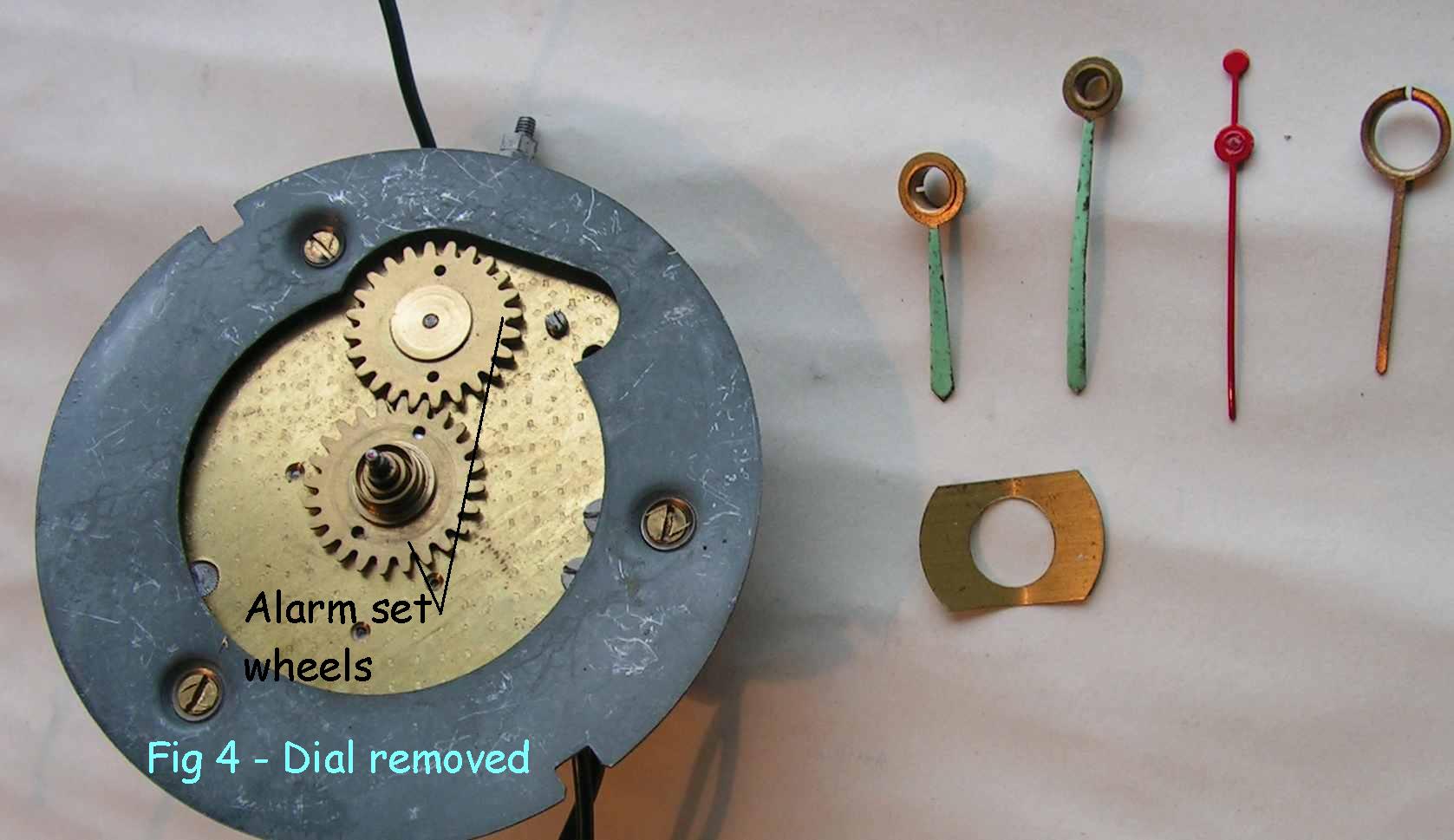
The dial is held on with two tags; bend one of them gently to remove the dial and carefully retain the spring washer and wheel for the alarm hand. Take off the three screws and the dial plate will come off.
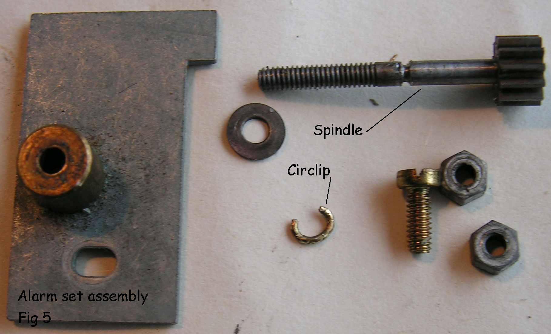
The alarm set assembly is retained by a single screw and washer. Remove it. It is necessary to remove the clip on the spindle so it can be cleaned and greased, it is a fiddly job! Undo the two nuts that hold the knob on – you will need two pairs of pliers for this. The clip is soft brass so it can be persuaded off with a knife and/or small screwdrivers.
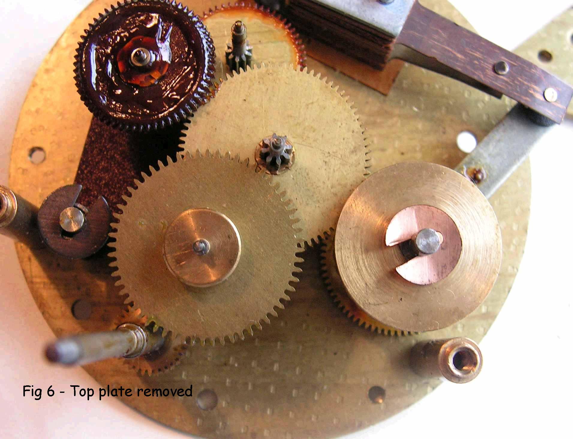
Now for the interesting bit! The top plate is only retained by one screw, as you have already taken off the other retaining pillars. Remove the screw and take off the top plate, and you will see the innards of the movement with all its wheels. Scary, huh?
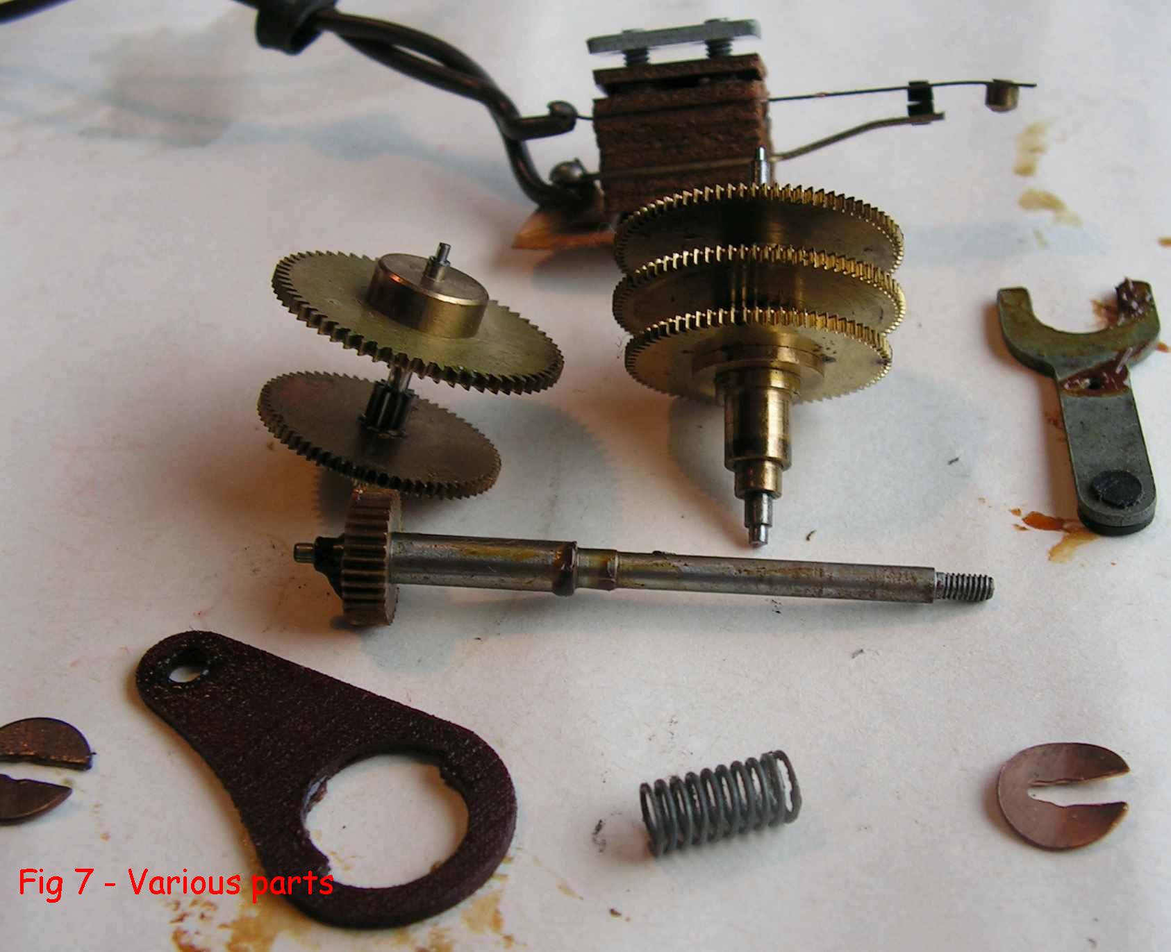
You can see the fibre wheel, second wheel and the centre stack of three wheels for the hands; on the bottom left are two wheels to form the reduction gearing for the minute (60:1) and hour hands (12:1).
Remove the three wheels that just lift off. The contact fork will just come off as well, with a bit of a wiggle. Remove the clip and spring on the anti-reverse cam (top left Fig 6) being careful to stop the spring doing an impression of Zebedee retiring for the night.
You should be left with the contact assembly and alarm set wheels.
At bottom right is the alarm arbor that only moves when you set the alarm – this is a contrate wheel that has axial teeth for the pinion shown in Fig 5 to set the alarm.
The wheel below this (Fig 9 for a better view) is geared with the hour wheel, and rotates in twelve hours.
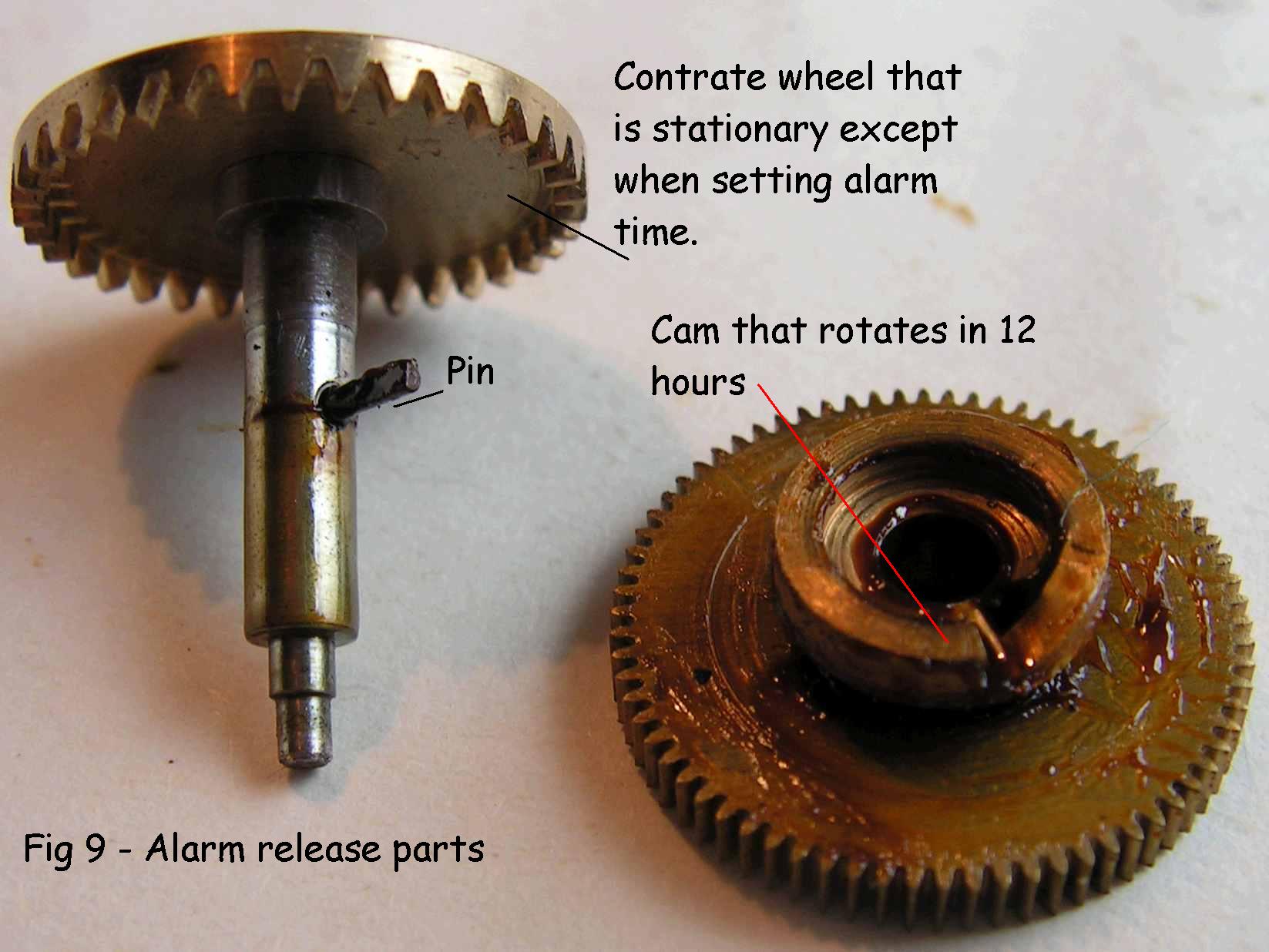
It has a cam with a notched step that operates against the pin on the arbor. To remove the latter, do not use any tools. Grip the contrate wheel and the wheel outside the plates, and carefully twist them, pulling at the same time, The outer wheel will come off, together with arbor and cam wheel.
Take the two screws out of the contact assembly and take the contact stack off the plate – keep everything together and put the screws back in so nothing gets lost.
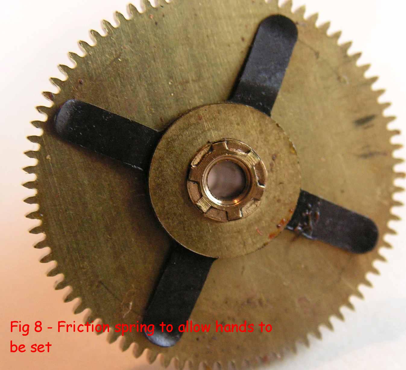
When you have looked at the wheels, you will see the one in the centre with a four-armed spring; this is to allow the hands to be set. The minute wheel carrying the pipe that holds the hand is attached to the wheel by the spring, and allows them to be moved independently (Fig 8)
Right – you have everything in bits – now for a bit of cleaning. Do not clean the motor field – give the iron bits a clean with kitchen paper, leave the coil alone.
Also, look at the contact points – if they are pitted, clean them with a fold of 400 wet-and dry. Don’t be too fussy as 240 volts will get past any slight dirt.
The dial can only be cleaned with soapy water, gently. The hands can be repainted if necessary:
Alarm hand – clean with metal polish and lacquer.
Minute and hour hands were originally painted with luminous paint that was radioactive; the nannies have banned it, but you can get luminous compound from clock material dealers. It is not that good, so use it if you want, or use some dayglo green paint. Paint the seconds hand red.
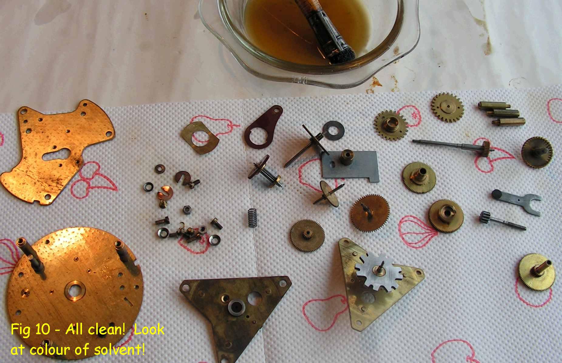
Everything we have not mentioned above except the rotor and its plate needs cleaning with solvent and a brush. Fill a small dish – ceramic, glass or metal and pour in say, 300ml of white spirit. Use a fairly short brush – like a 1 inch paint brush with the bristles cut off to leave ¾ inch length.
Get a few layers of kitchen paper and lay it out ready. Put each part in solvent, brush it, cleaning all the wheel teeth and pinion leaves, and leave it in the liquid.
After you have a few parts in there, take them out and leave them on the kitchen paper.
Then, when everything is out, use a lint-free cloth to give the pivots a bit of a polish. Examine the pinion leaves to see if they are scrupulously clean.
Clean the rotor and its plate separately, giving the rotor bearing a good wash. Dry thoroughly.
The pivot holes in the plates need ‘pegging out’ to rewove any solvent film. You can use special pegwood (it is dogwood) from a clock material dealer, but for occasional use, a clean piece of dowel / skewer / chopstick is fine. Sharpen it to a point and then twirl it in the hole – if the pegwood is clean, fine.
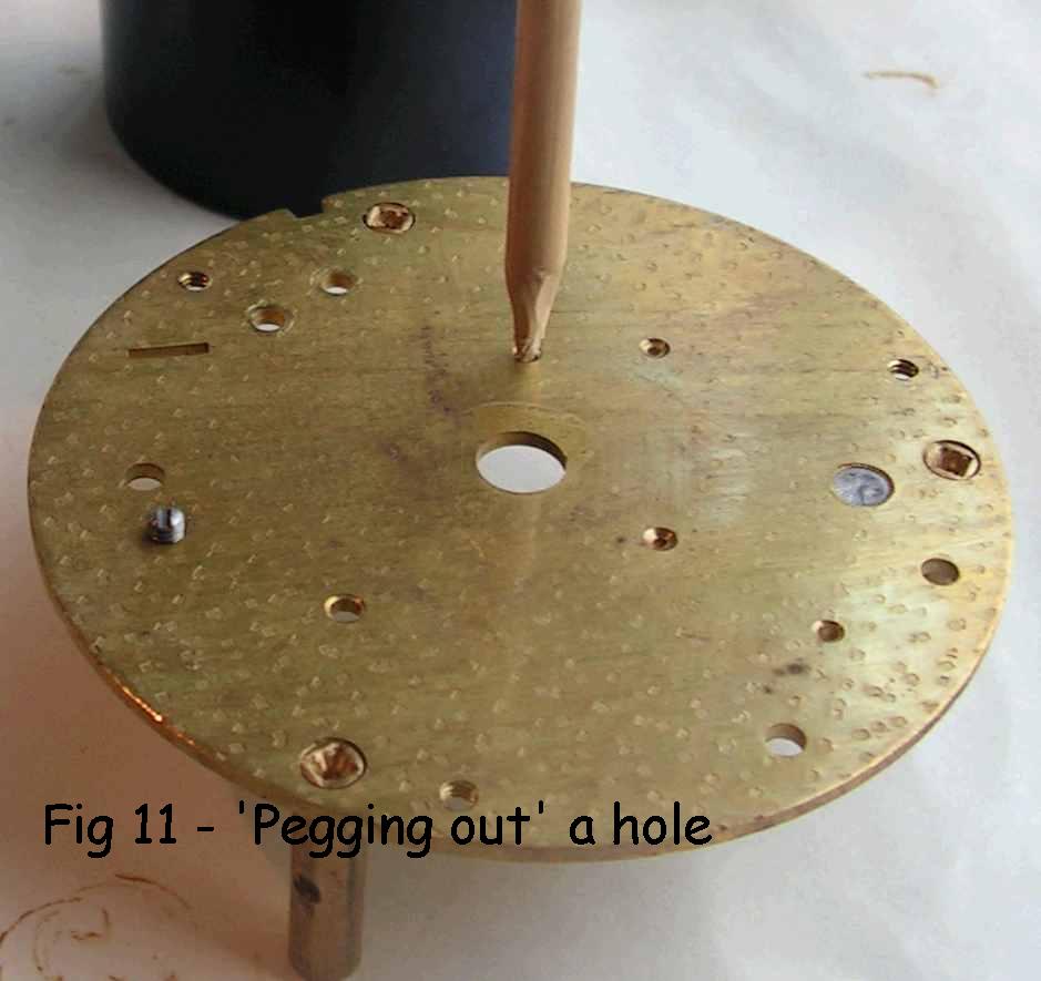
Electric clocks are less fussy about dirt or wear on the pivot holes, as the train is not under power, and the torque is increased as you go away from the power source (motor) unlike a weight or spring-driven clock that has power to the train all the time and whose torque decreases the further you go away from the power source.
Do not fingermark any of the parts excessively – fingerprints corrode brass, and the marks are difficult to remove.
Congratulations – you have now cleaned the clock, and just need to reassemble it.
Grab a coffee and when you come back, lay the bottom plate, pillars uppermost in something like a top from an aerosol can, just so the pivots can project downwards. If you forgot what the bottom plate was, it is Fig 10 bottom left.
Here we go – only lubricate the items that I say, sparingly, and use the recommended oil or grease above.
Screw the contacts on, and grease the alarm set arbor where the wheel goes. Grease the cam on the wheel and put it on.
Put the outer wheel on and twist it into position without using any tools. Place the arbor in its hole, grease the top of the ‘prongs’ of the fork and a touch on the hole under where the steel peg rocks.
The fork can be put in position (Fig 12) and you should be able to test the contacts now.
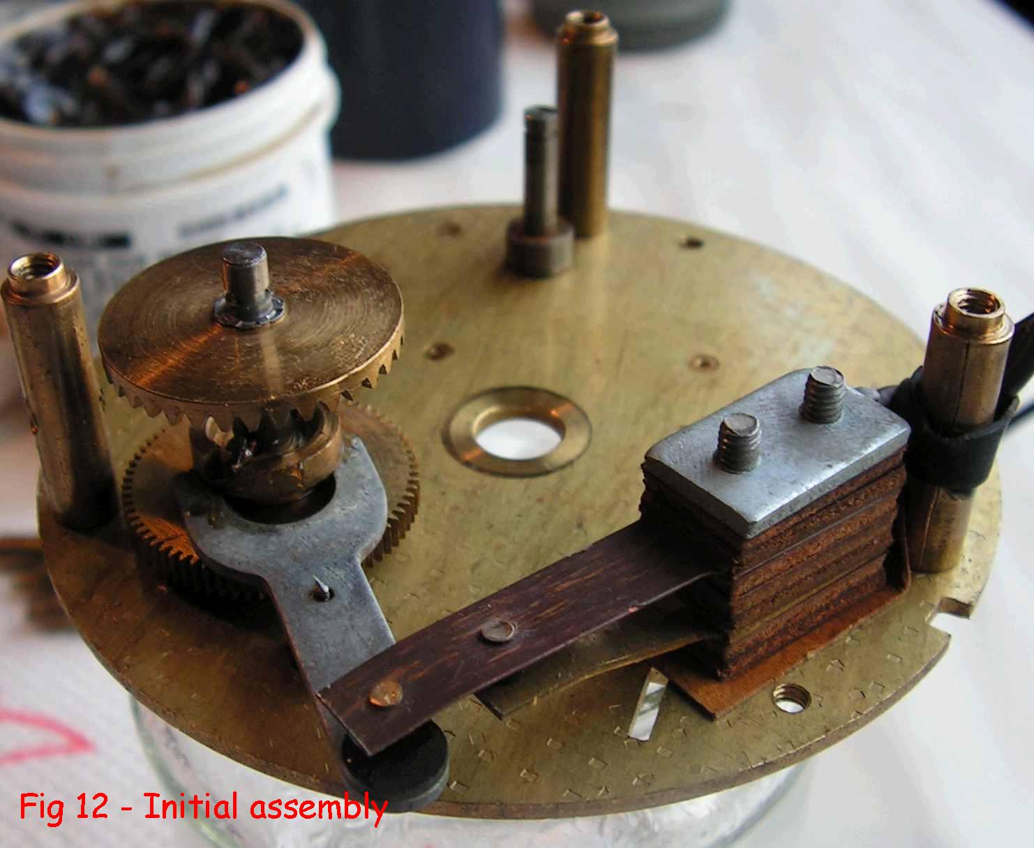
Holding the contrate wheel down, turn the cam wheel so the contacts open and close. When they close, the two contact points should be pressed firmly and squarely against each other, and when open, there should be about 3mm gap between the points, at least.
If not, do not adjust the nut and pin! The shorter of the contact springs is probably just bent a bit – straighten it.
The leads should have a rubber ring to tie the leads on to the nearest pillar. If missing or broken, a bit of heatshrink sleeving will suffice – heat it up with a soldering iron. We can now put all the wheels in position.
Put the anti-reverse cam on its post, noting position, and fit the spring and flat clip (Fig 13).
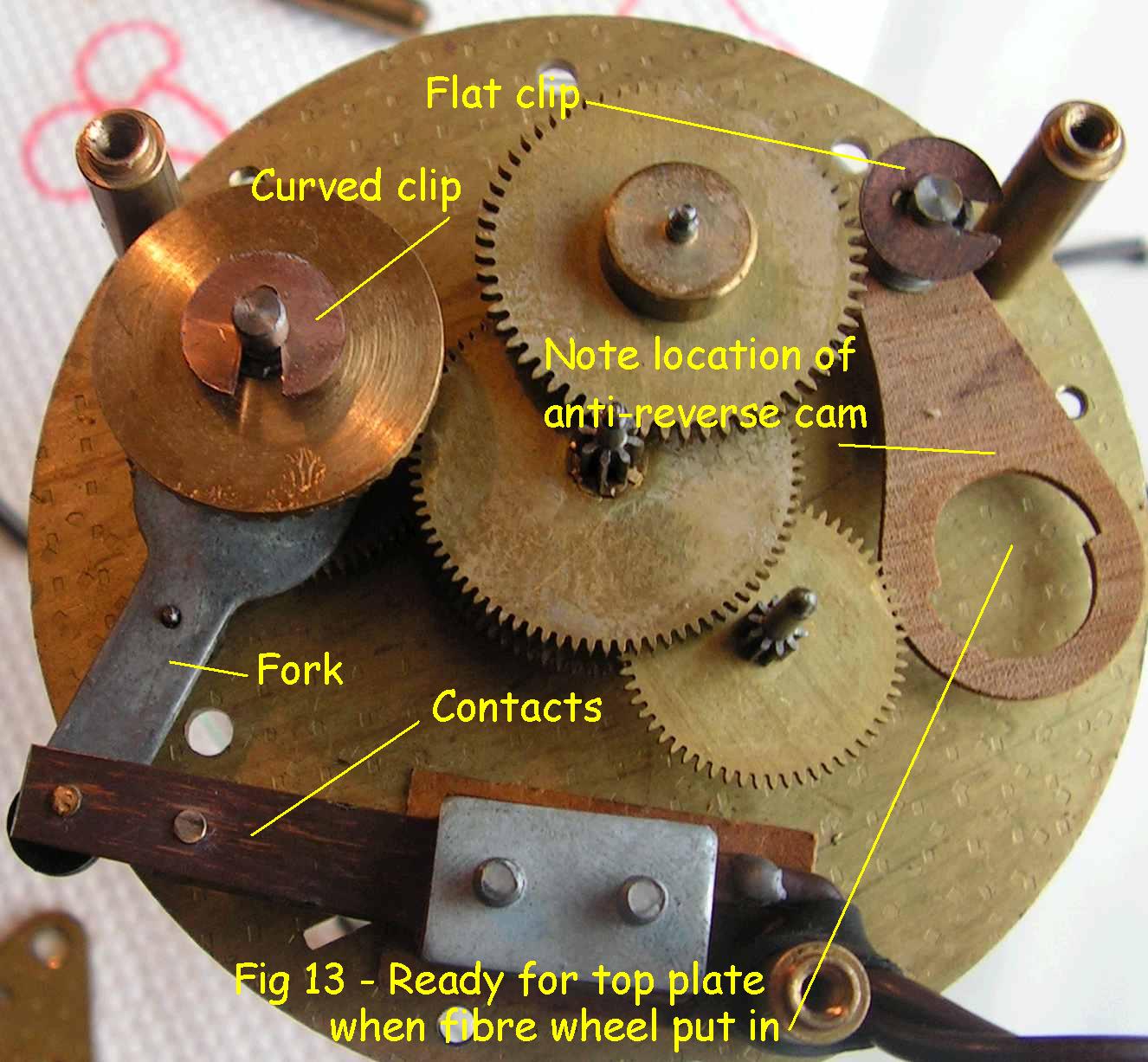
The stack of centre wheels can now be fitted, putting a drop of oil on the bottom pivot only. Then the two wheels at the top in Fig 13, oil bottom pivot again. The amount of oil on a pivot is very small indeed! Then the second wheel (bottom right) with a drop of oil. Put the clop on the alarm ser arbor – this is the curved clip and presses against the top plate.
The set-hands arbor needs to be placed with oiled pivots.
Finally, get the fibre wheel, put grease around the teeth, and another bit on the cam that operates the anti-reverse, oil the bottom pivot.
You have to oil the remaining pivots on the top, and drop the top plate on. Wiggle the pivots with tweezers until they drop in.
It may be useful to put the pillars in temporarily to hold things together. When everything is in, take any pillars off, and fit the screw that is nearest to the alarm arbor. There may be an earth lead then should be connected to it.
You need to oil the rotor bearing on the end where the pinion is, and spin the rotor to distribute it.
You can check that everything works by spinning the second wheel – the train should rotate freely, but only in one direction.
If you have only taken the rotor out, start from here
Put the rotor plate on, fit the spring on the pivot, and tighten the three pillars.
If you have separated the stator halves or removed the coil, reassemble, noting that the holes in the two halves should be identical and opposite, and that the ‘prongs’ on each side should be midway in the gaps.
Fit the stator leads uppermost, and ensuring that the three holes go on the protrusions on the plate – it will only go one way. Fit top plate and screws. A drop of oil is needed in the bearing, than the thrust bearing (small steel disc) followed by the spring can go on.
The alarm set pinion needs plenty of grease on its spindle, then you can put the brass circlip on, squeezing it with pliers. Lock the two nuts together
Put this assembly on the movement and fit screw and washer.
The dial plate and screws, alarm hour wheel and flat spring (concave side out) can go on followed by the dial.
The last thing is to put the hands on. Put the alarm hand on at exactly 12:00. Slowly turn the alarm set spindle and watch the cam and pin. Go slowly when it approaches the straight side of the cam, and stop when the contacts close with an audible click.
Put the minute hand on temporarily at about 12 minutes to then turn the knob to exactly 12. Take hand off, place hour, minute, than seconds hands on. The first two just push on, the seconds hand will need a tap with a piece of wood. Make sure that all hands are clear of each other, bending carefully if necessary.
You need to check that the clock works, first. I use a device called a Rendar Safeblok that I have had for years – it allows things with just leads to be connected safely to the mains and consists of three spring loaded clips that cannot be accessed until the cover is open and this switches the mains off. Whatever you use, make sure you do it safely.
When you apply power, the fibre and second wheel should be visibly rotating and the seconds hand should move. You may be able to see the wheels starting backwards and being bounced forward by the anti-reverse cam.
That is it – hopefully you have learnt how to get your clock working!